PRODUCTS
Genesis Cables & Interfaces - The Design
GENESIS ABSOLUTE FIDELITY INTERFACES ARE DESIGNED AROUND TWO PRINCIPLES – FIRSTLY, DO NO WRONG; AND SECONDLY, BALANCE.
Cable objectivists will have us believe that other than the parameters of resistance, inductance and capacitance, all cables will sound the same. It can be proven that as long as the cable is within reasonable parameters, differences will not be audible. Unfortunately, we do and can hear a difference in cable design.
The problem is not that some cables sound better than others. The problem is that they sound different. This is further compounded by the fact that all of us perceive sound differently.
The problem is not that some cables sound better than others. The problem is that they sound different. This is further compounded by the fact that all of us perceive sound differently.
GETTING THE BASICS CORRECT
Cable engineering is a well-understood science. That is why engineers are able to design cables to pass higher and higher speeds for computer networking, and higher and higher current for power transmission. For example, a Cat7 cable allows 10 Gigabit Ethernet over 100m, and is rated for a transmission speed of 600MHz. That is far, far above any frequency needed for audio.
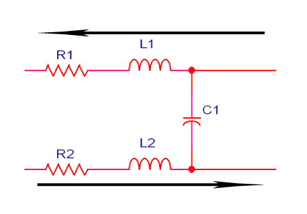
No cable is perfect, and any loudspeaker cable or interconnect can be modeled as follows:

THERE ARE THREE KEY ELECTRICAL PARAMETERS THAT ARE ALL EASILY UNDERSTOOD.
1) RESISTANCE
Resistance, R1 and R2 can be determined by size and material. 12 awg stranded copper wire has a resistance of 5.3ohm per kilometer (1.6ohms per 1,000ft). Go up to 10awg and it falls to 3.3 ohm/km, go down to 14awg and it rises to 8.5 ohm/km. Purity makes a minuscule difference to the resistance above about 99.5% pure. Silver has about 5% lower resistance than copper all else being equal.
Pure resistance causes a voltage drop, and does not affect frequency response and phase characteristics of the signal. The resistance needs to be sufficiently low that the voltage drop from one end of the cable to the other is negligible when terminated into the expected impedance.
2) INDUCTANCE
Whenever electrons flow through a conductor, a magnetic field will develop around that conductor. The more current that flows, the stronger the magnetic field. This magnetic field stores energy, and when the current stops, the collapse of the field returns energy to the conductor. Since this occurs between the amplifier and the loudspeaker, the sonic result is a smearing of detail.
The measure of this effect is inductance, and high inductance causes a cable to store and release current. Thus, a cable with high inductance can be regarded as “powerful” and “full bodied”. Intuitively, we can understand that this store and release of energy also causes a smearing of the signal.
When we build a cable, the two wires that carry current in opposite directions can be placed close one another so that the inductance can almost cancel out. The closer the two wires are to each other, the greater the cancellation effect and loop inductance can approach zero.

3) CAPACITANCE
Whenever a voltage exists between two separated conductors, an electric field will exist between those two conductors. The two conductors with the insulator in between will act as a capacitor which stores and releases energy.
Capacitors tend to resist changes in voltage between the two conductors. Hence, when the voltage is increased or decreased (as when a musical signal flows), the capacitor resists the change by drawing current from, or supplying current to the source of the voltage change in opposite to the voltage change. Since this is in parallel between the source and the destination, the capacitance acts as a shunt across the cable and the sonic result is the blunting or softening of transients and dynamics.
This effect can be measured in a cable as capacitance. A cable with higher capacitance can be said to be “sweeter” or “smoother” as a result. The closer the two conductors are together, the higher the capacitance.
A BALANCE NEEDED
Of the three electrical parameters of a wire, a balance is needed, and this balance can be optimized to make the cable as transparent as possible. While the range of inductance (micro-Henrys) and capacitance (pico-Farads) are sufficiently small that they should not result in significant frequency response distortion, we can hear the store and release of energy as distortion in the soundstage, a smearing of micro-dynamic detail and a loss of focus.
Some cables are optimized for the lowest possible inductance at the expense of high capacitance. It is easy to recognize these cables as they will have multiple insulated conductors that are tightly braided or spiraled together. The more expensive they are, the more conductors there are, and the higher the capacitance!
Other cables are optimized for the lowest possible capacitance at the expense of high inductance. These easily identified as they will have two conductors that are widely spaced and held apart. In these cables, a larger conductor results in lower inductance, but not by enough that it matters much.
Instead of reducing one at the expense of the other, finding the right balance is key.
MORE INFORMATION
Cable & Interface Design
FAQ – Interview with Designer Gary L Koh
Absolute Fidelity Interfaces Brochure (PDF 192KB)
Gary Koh’s ‘underground’ interconnects and speaker wires stand shoulder to shoulder, or nearly so, with the most transcendent and truly expensive cables which constitute the top of contemporary audio cable performance.”
– Jim Merod, Positive Feedback Online
